
In high-performance engines, measuring cylinder head flow is an important step in maximizing power output. For small block Chevy (SBC) engines, accurately measuring head flow can be difficult, but it is essential to achieving optimal performance.
Head flow measurement measures the air flowing through the cylinder head at a given valve lift and pressure. This information can then use to calculate the engine’s potential power output and identify weak areas in the valve train.
There are several methods for measuring SBC head flow, each with its advantages and disadvantages. We will explore different methods of measuring head flow and provide a step-by-step guide to measuring head flow on an SBC engine.
We will discuss the tools for accurate measurements, including flow benches, manometers, and digital micrometers. We’ll also cover all the details on how to measure SBC head flow like a pro.

Tools Required For Valve Lapping
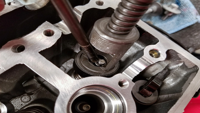
Valve lapping is an important task that ensures the smooth operation of an engine. It is necessary to have the right tools to perform this task properly. The first tool required for valve lapping is a valve-lapping compound.
This compound is a paste use to grind the valve and seat together. It comes in various grit sizes and is essential for achieving a smooth and even finish. The next tool required is a valve lapping tool. This tool uses to apply pressure to the valve while it is being lappe.
It is available in various sizes to fit different valve stems. A valve spring compressor also requires to removal the valve spring and retainer. This tool design to compress the spring, allowing the valve to remove easily.
A valve guide removal tool is also necessary to remove the valve guide from the cylinder head. This tool ensures that the guide removes without damaging the cylinder head.
How To Measure SBC Head Flow – A Step-By-Step Guide
Measuring SBC (Small Block Chevy) head flow involves determining the airflow capacity of the cylinder heads. Here’s a general procedure to measure SBC head flow:
1.Remove the cylinder heads: Start by removing the cylinder heads from the engine block following the manufacturer’s guidelines or standard procedures. Ensure the heads are clean and free from any debris or obstructions.
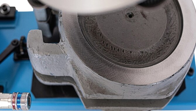
2.Set up the flow bench: Prepare a flow bench, which is a specialized device used to measure airflow. The flow bench consists of a calibrated flow meter and a fixture that holds the cylinder head securely in place.
Attach the cylinder head to the flow bench: Mount the cylinder head onto the fixture of the flow bench, ensuring a tight and secure fit. Make sure the head is properly aligned and oriented to replicate its installation on the engine block.
3.Establish the test parameters: Set the desired test parameters on the flow bench, such as the valve lift, test pressure, and test duration. These parameters may vary depending on the specific flow bench and the purpose of the testing.
4.Measure airflow at different valve lifts: Start the flow bench and gradually increase the valve lift while measuring the airflow capacity at each specific lift increment. The flow bench will provide readings indicating the amount of airflow passing through the cylinder head at different valve lifts.
5.Record the data: Take accurate measurements of the airflow rates at each valve lift increment. Ensure that all relevant data, such as valve lift, airflow rate, and corresponding cylinder head identifier, is recorded for future reference and analysis.
6.Repeat the process: Repeat the airflow measurement procedure for each intake and exhaust port of the cylinder head. This allows you to gather comprehensive data on the head’s flow characteristics across all ports.
7.Analyze the results: Once the flow testing is complete, analyze the data to assess the cylinder head’s flow performance. Compare the flow rates at different valve lifts and ports to identify any variations or restrictions in airflow. This analysis can help evaluate the efficiency and potential limitations of the cylinder heads.
It’s important to note that measuring SBC head flow requires specialized equipment and expertise. Professional flow bench operators or engine builders often perform these tests using dedicated flow bench systems.
Cleaning The Valves And Cylinder Heads
Regular maintenance of your vehicle’s engine is essential for optimal performance and longevity. Cleaning the valves and cylinder heads is a crucial part of engine maintenance that cannot be ignored.
Over time, debris and carbon deposits can build up on the valves and cylinder heads, compromising efficiency and causing power loss and engine failure. To prevent this from happening, it is recommended that you clean your valves and cylinder heads periodically.
This process involves removing the cylinder head, cleaning the valves and ports, and replacing worn or damaged components. Remember that this is a complex and time-consuming process requiring specialized tools and expertise.
Therefore, it is advisable to seek the services of a professional mechanic to perform this task. They will use specialized tools and techniques to remove the dirt and carbon buildup from the valves and cylinder heads, ensuring your engine runs smoothly and efficiently.
Preparing The Lapping Compound
Preparing the lapping compound is crucial in achieving a smooth and polished surface on metal parts. The process involves mixing abrasive particles with a liquid binder to create a paste-like substance that can applie to the metal surface.
The first step in preparing the lapping compound is to select the appropriate abrasive particles. The size and hardness of the particles will depend on the material being lapped and the level of precision required.
Once the abrasive particles have been selected, they are mixed with the liquid binder, which can be water, oil, or a specialized lapping compound solvent. The ratio of abrasive particles to binder will also vary depending on the desired level of abrasiveness.
The mixture is then stirred thoroughly until it reaches a consistent texture. It is important to note that the lapping compound must be stored in an airtight container to prevent it from drying out or becoming contaminated. Before application, the surface to be lapped must be thoroughly cleaned and dried to ensure optimal results.
Applying Lapping Compound To The Valves And Cylinder Heads
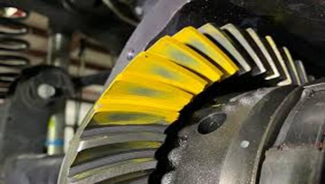
When it comes to maintaining an engine’s performance, one of the most important tasks is to ensure that the valves and cylinder heads are in good condition. Applying a lapping compound is a crucial step in achieving this goal.
A lapping compound is a type of abrasive material that design to smooth out any imperfections on the surfaces of the valves and cylinder heads. The process involves applying a small amount of the compound to the valve face or cylinder head surface and then rotating the valve or head back and forth to create a smooth, even surface.
The numerous benefits of applying lapping compound to the valves and cylinder heads. For one, it helps remove any carbon buildup that may be present, improving the engine’s overall performance and fuel efficiency.
Additionally, it can help reduce engine noise and vibration, making for a more comfortable driving experience. However, it is important to note that applying a lapping compound is not a task that shoul taken lightly.
Checking The Valve Seal
Checking the valve seal is an important step in maintaining the efficiency and safety of any internal combustion engine. The valve seal is responsible for preventing oil and fuel from leaking into the combustion chamber, which can cause a host of problems, including decreased engine performance, increased emissions, and potential safety hazards.
First, carefully locate and remove the valve cover to check the seal. Look for any oil or fuel leakage around the valve stem and seal.
If there is evidence of leakage, the valve seal may worn or damage and will need to replace. Another way to check the valve seal is to perform a compression test. This involves threading a compression gauge into the spark plug hole and turning the engine over a few times.
If the compression reading is low, it may indicate a faulty valve seal. Regularly checking the valve seal can prolong the life of the engine and prevent costly repairs down the road.
Reinstalling The Valves And Cylinder Heads
Reinstalling the valves and cylinder heads is a critical step in the engine rebuilding. It is important to take the time to ensure that everything properly aligne and torqued to the manufacturer’s specifications.
A common mistake is to rush through this step, leading to leaks, performance issues, and even engine damage. The first step in reinstalling the valves is to clean and inspect them for any signs of wear or damage. They should then lappe to ensure a proper seal against the valve seats.
The cylinder heads should also thoroughly cleane and inspected for cracks or warping. Once everything is deemed to be in good condition, the valves can be installed, followed by the valve springs, retainers, and keepers.
The cylinder heads can then bolte back onto the engine block using a torque wrench to ensure proper tightness. It is also important to lubricate the camshaft and rocker arms before reinstalling them.
Adjusting Valve Clearances
Adjusting valve clearances is essential to maintaining an engine’s performance and longevity. Over time, the valves in an engine can become worn and may not close properly, causing a loss of power and even engine damage.
To adjust valve clearances, you need to remove the valve cover and use a feeler gauge to measure the gap between the valve stem and the rocker’s arm. If the gap is too large or too small, you must adjust it by loosening the lock nut and turning the adjusting screw until the correct clearance achieve.
It is crucial to follow the manufacturer’s specifications for valve clearance settings and ensure that all the valves adjust evenly. Failure to do so can result in engine misfires, overheating, and other issues. Adjusting valve clearances is not difficult, but it requires some knowledge of engine mechanics and the right tools.
Break-In Procedure
A break-in procedure is essential to ensure the longevity and optimal performance of any new engine or machine. The process involves gradually increasing the load and stress on the engine or machine.
Allowing its internal components to adjust and settle into their proper places. The break-in procedure is crucial because it helps to prevent premature wear and tear, overheating, and other potential damages that could affect the engine or machine’s performance and lifespan.
Generally, a break-in procedure may take anywhere from a few hours to a few hundred hours. Depending on the type and size of the engine or machine. During the break-in procedure, following the manufacturer’s instructions carefully and avoiding pushing the engine or machine too hard too soon is important.
This process includes gradually increasing the RPMs, avoiding high loads, and allowing the engine or machine to cool down periodically. It is also important to keep an eye out for any unusual noises, vibrations, or warning signs that could indicate a problem.
Troubleshooting Valve Lapping Issues
Valve lapping is an essential process in the automotive industry, where the valves grow to fit the valve seats correctly. However, valve lapping issues can arise, leading to engine problems, including misfires, low compression, and poor fuel efficiency.
Troubleshooting valve lapping issues requires a thorough understanding of the process, including the tools and techniques used. One common problem is incorrect valve seating, where the valves not correctly grown to fit the valve seats, leading to poor compression and performance.
This issue can resolve by re-grinding the valves to ensure proper seating. Another issue is uneven grinding, where the valve surface is not smooth, leading to oil leaks and poor performance.
This problem can resolve by using a finer grinding compound and taking more time to ensure even grinding. Additionally, valve lapping issues can arise from using the wrong valve lapping compound, causing damage to the valves and seats.
Conclusion
Understanding how to measure SBC head flow is essential for any engine builder or performance enthusiast. Accurately measuring head flow can help identify any restrictions in the intake and exhaust ports, allowing for the optimization of the engine’s airflow and increase in power.
However, it is important to note that the process requires technical expertise and specialized equipment, making it best left to professional engine builders. Considering these factors, one can ensure that their engine operates at its highest potential and delivers the best performance possible.
Frequently Asked Questions
1.What Is The Importance Of Measuring SBC Head Flow, And How Does It Impact Engine Performance?
Ans: Measuring SBC (Small Block Chevy) head flow is important because it provides information about the engine’s airflow capacity. The rate of airflow through the engine is a crucial factor in determining the engine’s power output.
2.What Tools And Equipment Are Required To Measure SBC Head Flow Accurately?
Ans: The following tools and equipment required:
- Flow bench: A flow bench use to measure the amount of air flowing through the SBC head.
- Airflow meter: An airflow meter use to measure the amount of air flowing through the head.
- Manometer: A manometer use to measure the pressure difference across the head.
3.What Common Nistakes Or Errors Can Occur When Measuring SBC Head Flow?
Ans: Some common mistakes or errors when measuring SBC (Small Block Chevy) head flow include improper or inconsistent port preparation, inadequate or inconsistent cylinder head mounting, incorrect or inconsistent valve lift and timing, inadequate or incorrect airflow measuring equipment, and inaccurate.
4.What Are Some Typical Values Or Ranges For SBC Head Flow Measurements?
Ans: The typical values or ranges for SBC (Small Block Chevy) head flow measurements can vary depending on the specific engine and modifications but generally fall between 180-280 CFM (cubic feet per minute) at 0.500″ of valve lift.
5.How Can The Results Of SBC Head Flow Measurements Use To Optimize Engine Performance?
Ans: The results of SBC (Small Block Chevy) head flow measurements can use to optimize engine performance by identifying any restrictions or inefficiencies in the flow of air/fuel mixture through the cylinder heads.


![5 Best Flowing 23 Degree SBC Head [Reviews With Buying Guide]](https://accuratepicker.com/wp-content/uploads/2022/03/Best-Flowing-23-Degree-SBC-Head.jpg)